Arduino's 16 GB VENTUNO Q Runs a 744-Billion-Parameter AI Model From an SSD, and It Took 7 Minutes to Name Three Planets
Arduino's VENTUNO Q board, with just 16 GB of RAM, successfully ran a 744-billion-parameter AI model by streaming it from an SSD. It's slow, taking seven minutes to name three planets, but…
JBR-001 is an open source desktop robot that sees and recognizes the objects in front of it, then reacts with movements, sounds and animations. It was created by syntheticAIdata and built around the Arduino UNO Q 2GB. Inside there are three servos, a camera, a distance sensor, a buzzer and an animated display. So it is not yet another blinking ornament: it is a platform for experimenting with robotics, computer vision and edge AI on a workbench.
Assembly starts from a body of 3D-printable parts that house the board and the rest of the electronics. The head contains the camera, mounted so that it looks straight ahead of the robot. On the back of the same head sits a Modulino Distance, which continuously measures the distance to nearby objects. The arms and the rotation of the head, on the other hand, come from three servos. The mechanics are therefore easy to replicate for anyone who already has a 3D printer at home.
Overview of the hardware project
Servo pins and distance thresholds in the code
The three servos split the tasks: one rotates the head, the other two control the arms. In the code the pins are HEAD_SERVO_PIN = 9, LEFT_ARM_SERVO_PIN = 10 and RIGHT_ARM_SERVO_PIN = 11. The rest positions are all at 90 degrees, so HEAD_CENTER = 90, LEFT_ARM_CENTER = 90 and RIGHT_ARM_CENTER = 90. The servos also use a separate external power supply instead of drawing power from the UNO Q: a forced choice when three motors start at the same time.
The distance sensor decides when the robot should notice someone. In the code the detection threshold is DETECTION_DISTANCE = 200.0, while the reset one is RESET_DISTANCE = 250.0. The units are not specified in the project material, so they should be checked on the bench before trusting them. The margin between the two thresholds prevents the robot from switching on and off continuously when someone stays right on the boundary.
Heartbeat on the display, a greeting in notes and the vision model
The robot’s responses go through three different channels. The LED matrix display is driven with bitmaps of 8 rows by 13 columns, the two used for the small and large heart. In the heartbeat animation the delays are 120, 100, 160 and 700 milliseconds, and the last long gap gives the sense of the pause between one beat and the next. The sound greeting playHello instead uses the notes 523 Hz (C5), 659 Hz (E5), 784 Hz (G5) and 1047 Hz (C6), that is a C major arpeggio rising by one octave.
The most interesting part comes from the camera mounted in the head. It connects through a USB-C hub and gives the robot a front view of its surroundings. The captured images can be processed on the UNO Q with a trained computer vision model: this way JBR-001 does not just understand that something is nearby, but identifies the object and uses the result to decide how to react. Consequently the same hardware can turn its head, move its arms, change the image on the display or play a short sequence.
Arduino UNO Q 2GB as the robot’s brain
Modulino Distance for continuous distance measurement
Modulino Motors for motion control
Modulino Buzzer for sound sequences
Arduino USB-C Hub (8 in 1) to connect the camera
Three servos for head and arms
Camera mounted in the head
3D printer for the body parts
On the software side you need Arduino App Lab and the JBR-001 source code, plus a trained computer vision model for object recognition. The project has 1805 views and 2 respects. Anyone who wants to rebuild it starts here: the maker syntheticAIdata’s site, where the code and the instructions to replicate the build are. For the servos, an RC servo control module simplifies the wiring when the channels to drive grow. The project’s distance sensor is a Modulino, and as an alternative you can consider a ToF laser sensor for close-range measurement. The board everything runs on is the 2GB version, while the catalogue also lists the Arduino UNO Q 4GB in a complete kit: same family, more memory for vision models.
Linux mascot Tux the penguin was created by Larry Ewing using GIMP
The idea that changed how we build technology
Happy Linux Day, Arduino Fans!
Since 1991, Linux has helped popularize open-source software. And then Arduino, inspired by that, extended that open source concept to hardware with its own launch in 2005. The open-source movement did not stop at the screen; it also influenced the development of physical computing. As we celebrate Linux Day, we honor the collaborative ethos that helped shape the internet and the Arduino movement. Just as Linux democratized software by opening the kernel, Arduino liberated hardware from corporate labs, proving that when we freely share our blueprints from C++ to circuit schematics, we empower a global community to build the future together.
Linux meets the physical world
Imagine building an autonomous robot where the engineering challenge isn’t just running computer vision, but seamlessly bridging that user-space intelligence with bare-metal physical execution. The Arduino® UNO Q board solves this by unifying a Qualcomm Dragonwing QRB2210 microprocessor running a full Debian Linux environment with an STM32U585 microcontroller for real-time, deterministic hardware control. This dual architecture gives developers the established capabilities of Debian’s package ecosystem and networking stack for AI workloads, while the bare-metal microcontroller supports real-time control of motors, sensors, and actuators, including sub-millisecond operations where supported by the applicable configuration and workload.
This integrated architecture is designed to reduce the friction associated with bridging separate computing and control hardware.By unifying real-time control with Debian’s robust software ecosystem, the UNO Q can help developers focus on building applications across robotics, computer vision, and industrial automation.The platform illustrates how advanced computing and bare-metal execution can be combined in an open, collaborative development environment.
From ideas to real world builds
The real power of open source comes to life in what people can create with it. Across the Arduino community, makers and developers can explore a broad range of possibilities, from desktop companion robots to autonomous systems that tackle everyday problems, and beyond. Whether they’re experimenting with the UNO Q or Arduino® VENTUNO Q board, sharing their ingenuity through competitions and hackathons, or inspiring others with creative builds, these projects turn bold ideas into working solutions. Here are a few builds that caught our attention, built by community members using Arduino hardware and Linux-based capabilities.
Curie: An AI companion for ADHD and cognitive focus grounding
Curie is an open-source desk companion built on UNO Q, intended to interact through audio and vision features to help users begin tasks and maintain focus. Learn more.
Autonomous pantry assistant
An autonomous edge AI assistant that identifies pantry products and reads their labels aloud for people with low vision. Learn more.
A robot arm that sees you
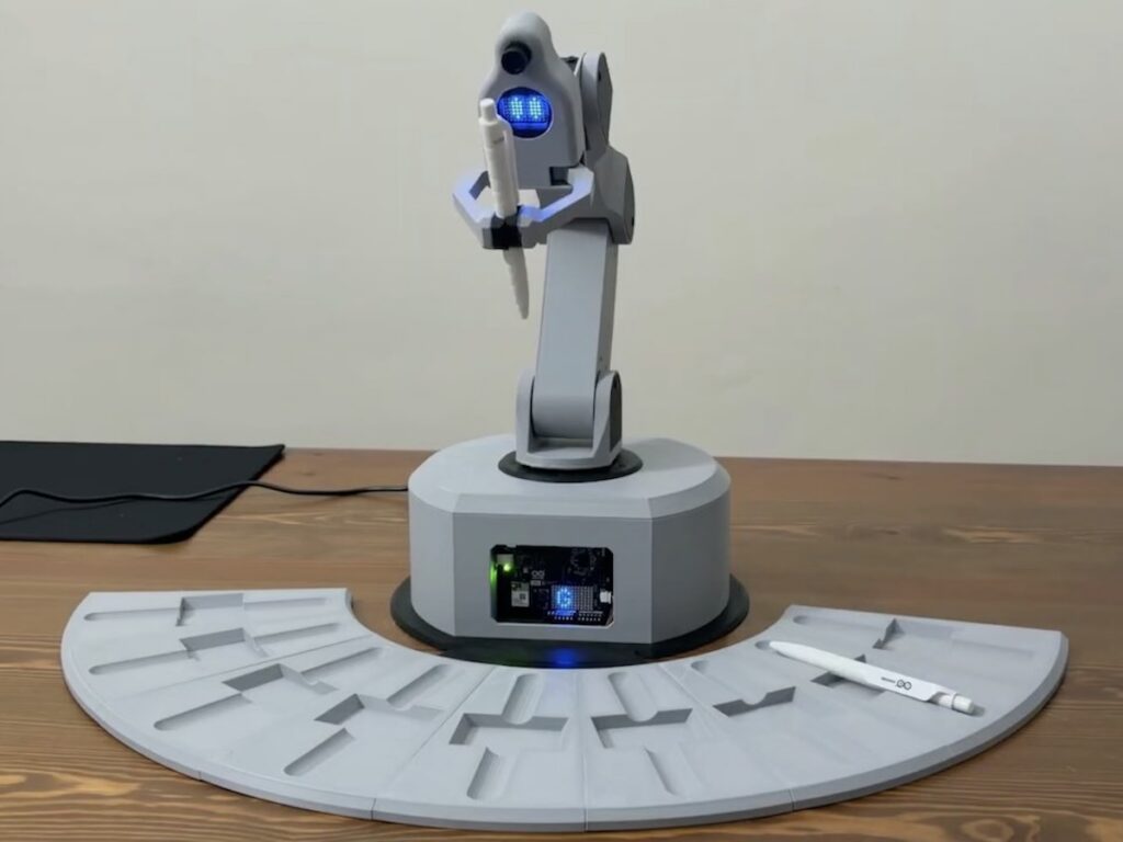
Imagine a robot arm designed to detect configured users and deliver selected objects. The arm runs on Feetech digital servo motors with a Waveshare control board, and a camera on the head handles the recognition. Learn more.
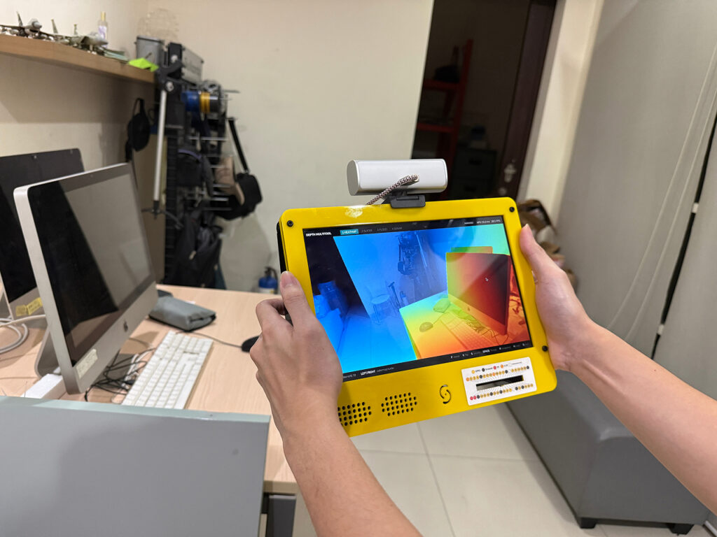
Depth multitool on the VENTUNO Q
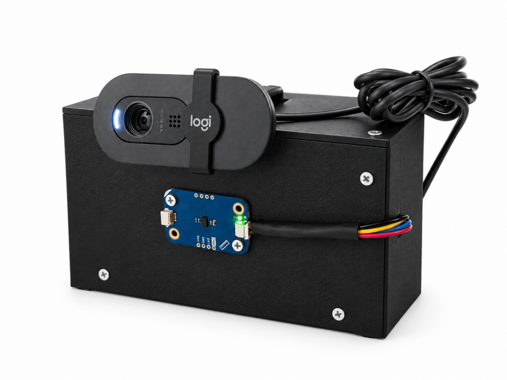
One ordinary webcam, a depth model on the VENTUNO Q NPU, and four visualization modes for estimating the distance of objects within the camera’s field of view. Learn more.
Building on open foundations
Many community projects build on open-source software and hardware. Arduino continues to strengthen that foundation with new hardware, software, and tools that give developers more ways to experiment, create, and solve difficult problems. The 2026 Arduino Open Source Report highlights this motion and key contributions from our vibrant, passionate community. Here are just a few of the highlights, reported by Arduino as part of its open-source ecosystem:
6 new open source hardware boards
11 new official libraries
Arduino® App Lab for UNO Q
The community led with:
1,218 new libraries, bringing the total to 8,754
6,602 new versions of libraries
420 new open source projects
The next chapter
As AI descends from the cloud to power the next generation of autonomous robots and edge devices, open-source development continues to play an important role in this area. The convergence of Linux, Arduino, and edge intelligence is helping enable new physical-computing applications, and it is the global community that will define what is possible. That is the true spirit of Linux Day: a brilliant, decentralized future we are building together.
Qualcomm branded products are products of Qualcomm Technologies, Inc. and/or its subsidiaries. Arduino, UNO, and VENTUNO are trademarks or registered trademarks of Arduino S.r.l.
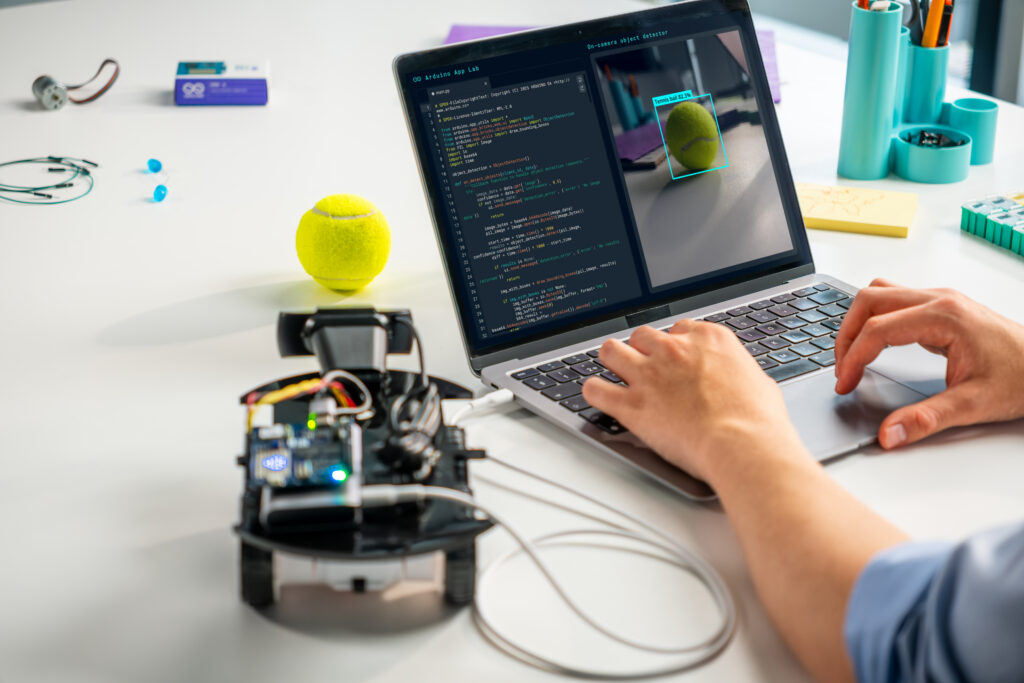
You build something great on your Arduino® UNO Q board. Now what? Arduino App Lab 0.11 is about taking your project further, whether that means shipping it to another board, getting help while you code, or teaching your device to recognize a tennis swing.
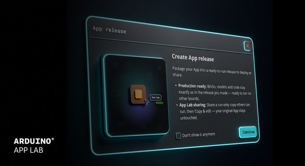
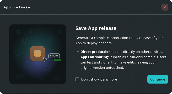
App Lab now supports exporting production grade “Apps Releases,” so your project built in App Lab can be packaged for deployment without leaving the tool.
How does it work?
1. Package an app into a ready-to-run file. 2. Install it on another board. 3. Run it on compatible third-party hardware included in the Works with Arduino program.
What’s the difference between this new App release and the export feature?
Export is great for sharing a project. An app release is designed to provide a consistent, ready-to-run package. An app release is a frozen, immutable package with locked dependencies to support consistent behavior across compatible devices. Sketches are pre-compiled, which can reduce startup times. Remote dependencies like AI models are downloaded at install time, which can streamline setup across multiple boards.
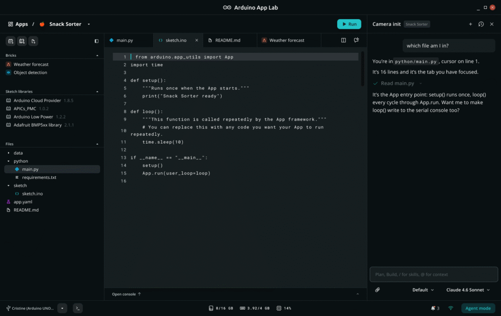
Chat with an Agent Panel next to your code to build, troubleshoot, and brainstorm ideas.
Agent Panel uses the app, files, and code open in your workspace as context, which can reduce the need to copy and paste or switch tabs. It will update files in your workspace as you chat with it in plain-language, and it keeps your chat history organized by app.
What’s the difference between the Agent Panel and Agent Mode?
Agent Mode, introduced in App Lab 0.10, is a full-window experience centered on the agent. You describe what you want and the agent creates and works on your app for you. The Agent Panel is a side chat that stays open while you work in your app. It uses the app and files you have open as context, updates them as you chat, and you run your app right there as usual.
New Pose Estimation Brick: teach your board the moves
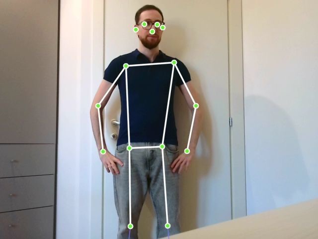
The new Pose Estimation Brick runs locally on your Arduino® VENTUNO Q and comes with two features: one with preconfigured capabilities and one that supports custom poses.
Preconfigured skeleton tracking and pose detection
The Brick tracks a 17-point body skeleton at up to 10 frames per second and draws a live overlay on your video stream. It also recognizes standard poses like standing, sitting, or arms up and down, without a separate model-training step. The demo app is just six lines of code.
Make it yours: teach it a custom pose
Need something more specific? Give the Brick a folder of photos of the pose you want, plus a folder of photos that are not that pose. No separate model-training step or additional tool is required. The photos are the whole input, and App Lab performs a recognition check before the app starts.
Want to recognize a tennis stroke? Provide representative photos to configure the custom pose.
Bring your own model
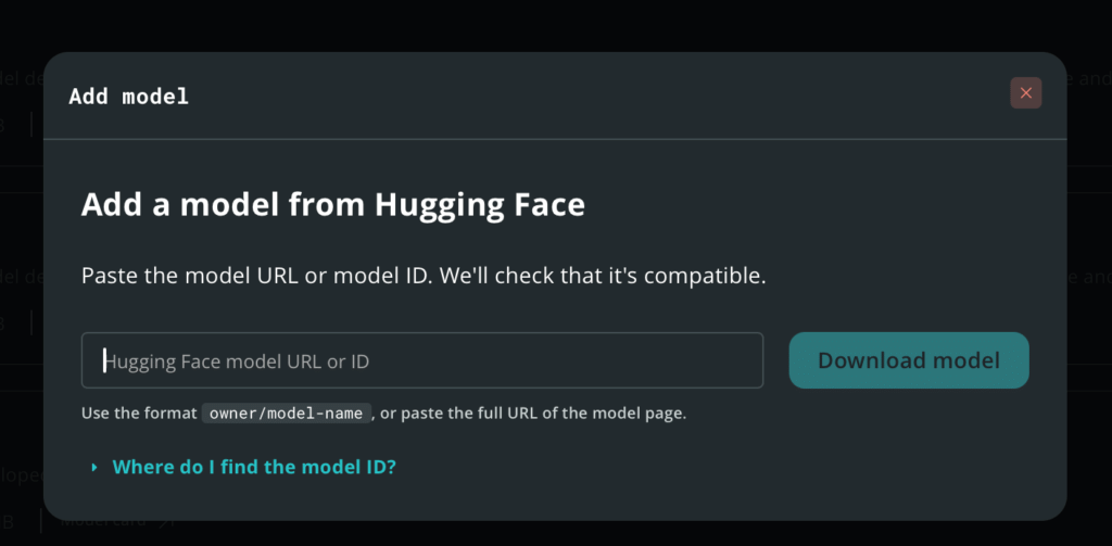
Add language models for the LLM Brick straight from Hugging Face, using a model ID or URL. App Lab checks that the model is compatible and selects a support quantization based on the model.
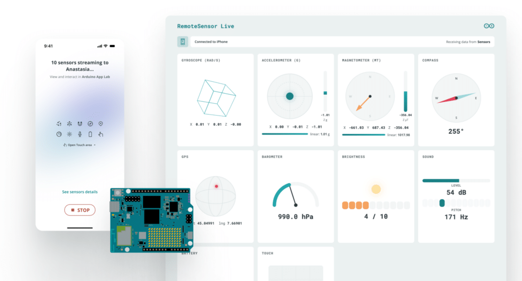
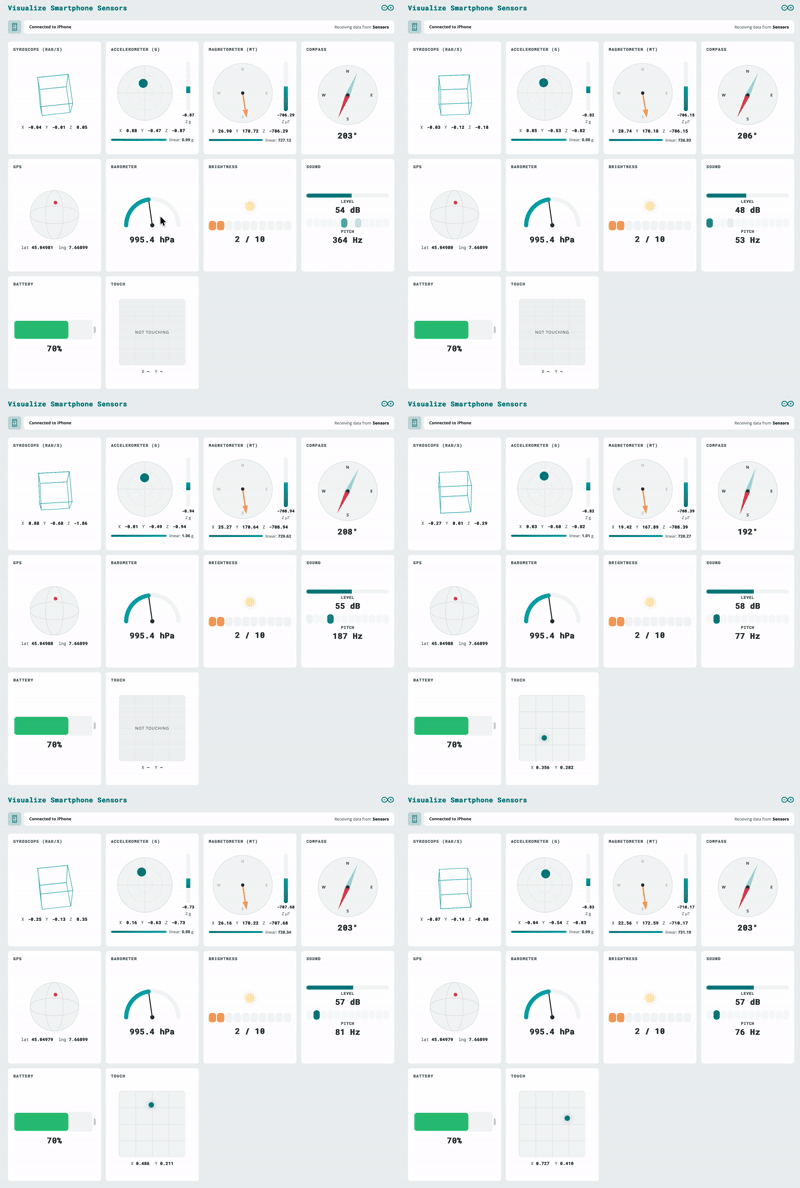
Microphone and IMU data now flow into App Lab through a new remote sensor peripheral, at high frequency over WebSocket, with password protection and encryption options. Data is sent as JSON, so you can define your own keys. Because it is built on WebSockets, compatible external devices can stream data to your board using the supported WebSocket interface, which can support remote-control and IoT use cases.
Know where you are, even when GPS struggles
In this short demo,AnthonyHebert andStefano Implicitoshow how easy it is to get started and put TPS to the test by findingAndyin the middle of a crowded show floor.
We showed the Qualcomm Terrestrial Positioning Service (TPS) running on UNO Q at The Things Conference 2026 on September 28th. It uses nearby Wi-Fi, cellular, and Bluetooth LE signals to support positioning while managing power consumption. A new TPS brick and example provide a way to evaluate the service.
Also in Arduino App Lab 0.1
VENTUNO Q flashing: flash your board from the built-in flasher in Settings.
Board extensions: select and configure the carriers and JHAT add-ons attached to your board from the Settings page.
Publish to Arduino Project Hub: upload your app as a project draft from the App menu.
Editor improvements: Find All References for Python and C++, YAML syntax checking, any file or folder name, and a separate console tab for each Brick container.
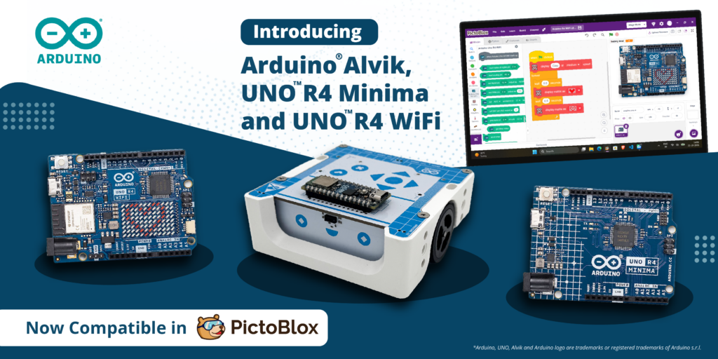
STEMpedia and Arduino bring block-based coding to the Arduino®UNO R4 WiFi and UNO R4 Minima boards as well as the Arduino® Alvik robot.
Every maker remembers the moment something they built first came to life: an LED blinking, a servo sweeping, a sensor reacting to a hand wave. Today, that moment gets a lot easier to reach thanks to a new collaboration between STEMpedia and Arduino!
We’re excited to reveal that PictoBlox 10.0, STEMpedia’s coding and technology creation platform, has expanded its Arduino compatibility to include the UNO R4 WiFi, UNO R4 Minima, and Alvik robot.
And what better place to celebrate this news than at Maker Faire Rome 2026? Join us from October 23rd–25th to explore the new integration and try PictoBlox for yourself!
From first-time coder to confident creator
Arduino has long been a starting point in electronics for makers, students and educators.PictoBlox brings a visual, drag-and-drop programming experience that helps users to focus on programming concepts without having to start with coding syntax. Together, they can help beginners go from “I’ve never coded” to “I built a working project” in a single session.
But PictoBlox isn’t just for beginners – or just for programming. Beyond block-based coding and Python, the platform is designed to let users explore AI and machine learning, experiment with tinyML and intelligent systems, program compatible robotics and electronic hardware, and develop IoT projects. It also supports game and animation development, opening up even more opportunities for hands-on creativity and experimentation.
Announcing the collaboration, Dhrupal Shah, CEO and Co-Founder of STEMpedia, said: “Great innovations begin with the freedom to experiment. By expanding Arduino board support in PictoBlox, we are making it easier for learners and makers around the world to turn their ideas into working projects.
“Students can create AI-powered projects and train their own Machine Learning models, making complex technologies more accessible. We’re excited to see how this collaboration inspires the global maker community to explore, build, and innovate.”
What you can do with PictoBlox and Arduino
Combining visual programming with Arduino hardware opens up all sorts of creative possibilities:
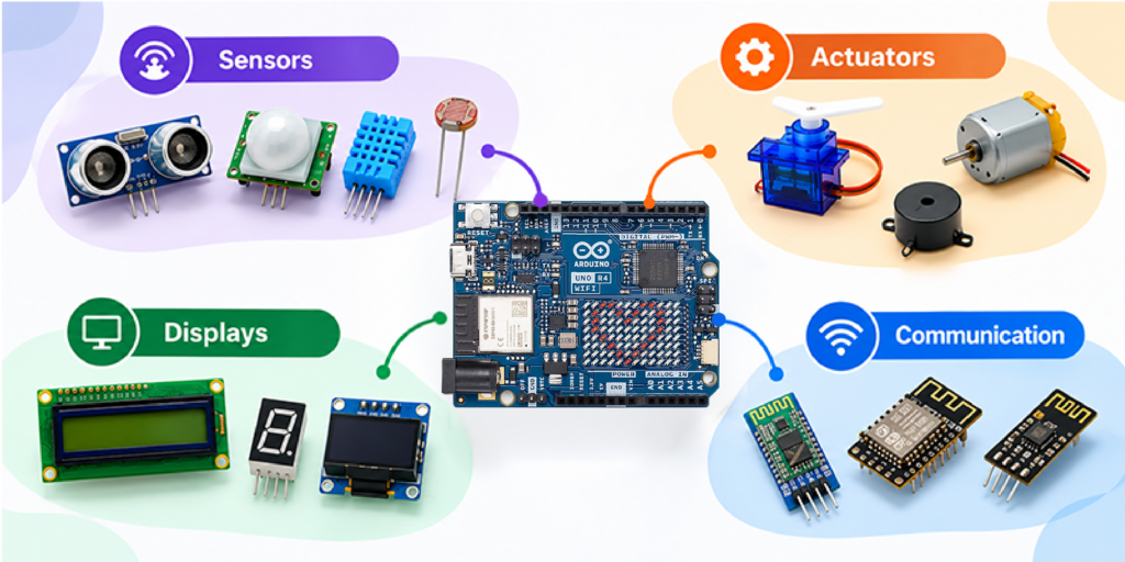
Program with blocks: snap together scripts instead of typing code, and see how your Arduino responds right away.
Work with sensors: read inputs such as an IR sensor and use them to trigger actions.
Control actuators: drive LEDs and servo motors from your scripts.
Go wireless: control your projects from a smartphone using Dabble, a project interaction and Bluetooth controller app.
By bringing together Arduino’s hardware ecosystem and PictoBlox’s versatile coding environment, the collaboration aims to make technology creation more approachable and open up new possibilities for the global maker community to learn, build, share, and innovate.
Built for classrooms, clubs and makerspaces
Whether you’re teaching in a classroom, running a coding club or experimenting in a makerspace, this expanded integration is all about trying to lower the learning barrier and open up new possibilities for creative exploration.
By helping reduce the need to manage syntax, block-based coding means learners can focus on developing essential skills like logical thinking, problem-solving and understanding how code works. And as their confidence grows, they can build on these foundations, explore text-based programming and take on increasingly ambitious projects within the Arduino ecosystem.
For educators, it’s a compelling combination: an approachable software environment and a familiar, well-supported hardware platform, with plenty of room for students to learn, experiment and grow – all in one workflow!
Get hands-on at Maker Faire Rome!
Heading to Maker Faire Rome this year? Be sure to stop by booth N.02, where you can see PictoBlox and Arduino in action, try out the new integration for yourself and chat with the team. We’d love to see you there!
Two Eyes, One Tiny Chip: This Open-Source Board Computes Stereo Depth So Your Arduino Doesn't Have To
Hardware hacker machinehum created 4reel, an open-source stereo vision board with two global-shutter cameras and a Rockchip RV1103 chip. It computes stereo depth on-board, offloading the task from…
Want real-world experience developing AI models and deploying applications using cutting-edge technologies such as the Arduino® UNO Q board? Qualcomm Academy has a new second-level program for you! The AI Associate Certification: Model to App is a hands-on, online, and self-paced program designed to provide experience with the end-to-end ML workflow, including data preparation, model creation, optimization, deployment, and on-device inference.
Through approximately five to six hours of build-along training, you’ll enjoy a combination of technical depth and practical application, helping you develop the confidence to create accurate, efficient, and production-ready AI solutions at the edge.
Three projects. One complete edge AI journey.
To achieve their certification, participants use a learning-focused development kit based on UNO Q to complete three real-world projects that span voice, vision, and sensor-based AI:
Wake Word Detection: Create and optimize a voice-enabled application that recognizes predefined wake words.
Person Recognition: Build a computer vision application that processes image data and performs real-time inference on an edge device.
Gesture Recognition: Train a model using IMU sensor data to detect and classify movements in real time.
Each project connects model architecture, training, validation, quantization, deployment, and application integration so learners can explore the ML lifecycle in practice.
Build skills for real-world edge AI development
By completing the certification, you will gain hands-on experience with developing ML models, preparing data, quantizing and optimizing models to explore tradeoffs among accuracy, latency, power consumption, and performance, and visualizing model graphs. You will also gain experience with AI development toolchains, explore MCU and MPU capabilities, develop real-time applications, and work with FastRPC communication for AI workloads.
The program is designed for developers and engineers, embedded systems professionals, IoT and robotics developers, students, and industry professionals interested in gaining practical experience with ML and edge AI. Learners should have basic Python skills, familiarity with an IDE, introductory knowledge of PyTorch and ML concepts, and prior hands-on experience equivalent to the Qualcomm Academy foundational AI certificate programs.
Flexible learning, practical results
The AI Associate Certification: Model to App is available online and can be completed at each learner’s own pace. You may purchase the program via Qualcomm Academy. After successfully completing the certification requirements, you will receive a Qualcomm Technologies certificate and badge that can be displayed on your CV and LinkedIn profile.
Start building – from model to app!
Take the next step in your AI development journey. Enroll in the AI Associate Certification: Model to App and gain hands-on experience applying ML concepts to applications running at the edge.
Visiting Maker Faire Rome (October 23rd–25th)? Make sure to stop by the Arduino booth to talk to the team about how you can get your AI Associate Certification: Model to App.
Qualcomm Academy is a program of Qualcomm Technologies, Inc. and/or its subsidiaries. Arduino and UNO are trademarks or registered trademarks of Arduino S.r.l.
An ATmega2560 with 8 KB of RAM can support a multitasking desktop environment, complete with games, file management and video playback. That is what Vladimir demonstrated by building a DIY laptop around an Arduino-compatible board with an ATmega2560, the Mega 2560 Pro Mini. The device measures 12x11x3.4 cm and packs a QWERTY keyboard, a 128×64 monochrome display, audio, microSD, an RTC and an 18650 battery into a 3D-printed enclosure. The firmware runs on FreeRTOS and offers real multitasking, with task switching via Alt-Tab. So a video that has been started keeps playing its audio while you play Sokoban.
The architecture of independent tasks is the core of the project. Applications receive events and draw through the UI engine, while the shell handles registration, stacks, switching and events. As a result, adding a new application does not require touching the others. A new task is a class with setup and loop plus a couple of methods for its menu entry and icon.
The UI engine and the applications on FreeRTOS
The interface engine handles forms, buttons, checkboxes, lists, input fields and dialogs. It takes care of key presses, tabbing, redrawing and the events sent to the owning task. On top of it run the ready-made applications:
file manager
video player
music player
clock
calculator
Sokoban
Snake
Game of Life
text editor
The ST7920 display is driven in parallel mode with a custom-written driver and a 1 KB video buffer in SRAM. The graphics functions range from a single pixel to text and XBM images. The AVR microcontroller runs at 16 MHz and everything runs on 8 KB of RAM, half of which is already taken up by global variables. That is why every byte of the buffer counts.
8×8 keyboard, debouncing and a 4-to-16 decoder
The keyboard has 64 keys in total, arranged in an 8×8 matrix that requires two 8-bit ports of the microcontroller. The keys were laid out in an 11×6 rectangle. Scanning happens column by column at hundreds of hertz, with software debouncing. In one revision a diode was added for each key and column selection moved to a 4-to-16 decoder. This way four pins are enough to select a column and the keyboard can expand to 16 columns.
24 fps video and XBM format plus MP3 in a single file
The video player uses a custom format with an XBM stream and MP3 in a single file. This way the player comfortably handles 24 fps video with audio, without keeping more in RAM than needed. The rest of the board is taken up by the RTC and the 18650 battery, which make the device self-contained. The enclosure was machined with a CNC3018 and 3D printed, while the schematics were drawn in EasyEDA.
Anyone who wants to rebuild the project will find the story of the work and the information to recreate it on the project page on Hackaday.io signed by Vladimir. Alternatively, an enclosure for an Arduino Mega can serve as a dimensional reference for the electronics, even though this laptop’s case is printed to measure.
When running UNO Q as a standalone single-board computer, navigating its Linux desktop environment doesn’t have to mean reaching for a standard mouse and keyboard. One of the most rewarding aspects of combining microcontrollers with a full operating system is the freedom to design custom physical interfaces – turning buttons, knobs, and joysticks into direct, tactile controls for your software.
To support that experience, we’re introducing the UNO Q SBC Controller Bundle. Designed for makers, learners, and innovators, this kit brings together hardware, software, and step-by-step guides to help you build a customized control setup.
What’s included in the box?
At the heart of the bundle is the dual-brain UNO Q 4GB board. To create a physical input layout as an alternative to certain traditional input functions, the kit includes a curated set of Arduino® Modulino nodes: Buttons, Joystick, Knob, and Pixels for dynamic visual feedback.
The included components connect through the Arduino®App Lab development environment. To give your finished project a clean, product-like appearance, we also offer a downloadable, 3D-printable enclosure that you can print or modify for your design.
Bringing physical control to your Linux workflows
Running Linux directly on your development board supports a range of potential applications, as we recently explored in our overview of what Linux unlocks on the UNO Q board. Whether you’re managing local Home Assistant dashboards, launching retro games, or controlling edge AI routines, physical controls provide another way to interact with your system.
Building your own controller offers a hands-on way to explore human-machine interaction, helping you learn how physical inputs translate into operating system commands. Thanks to the modular nature of the Modulino ecosystem, the setup is designed to be flexible – you can reconfigure supported input mappings or swap in compatible components as your project evolves. Detailed walkthroughs are already available here on Arduino Project Hub with instructions for assembling the featured configuration.
Completing your desktop setup
If you’re turning your UNO Q into a complete desktop station, a few optional accessories can round out your build. The Arduino®USB-C Hub (8 in 1) adds HDMI output, Ethernet, and extra USB ports, while the official Arduino USB-C Power Supply (45W) and Arduino USB-C Cable (24 pin) are designed to provide compatible power delivery for the UNO Q setup.
Head over to the Arduino Store to explore the new UNO Q SBC Controller Bundle, download the 3D-printable files, and start crafting your own custom hardware interface today!
Arduino, UNO, and Modulino are trademarks or registered trademarks of Arduino S.r.l.
By Marcello Majonchi, Chief Product Officer at Arduino
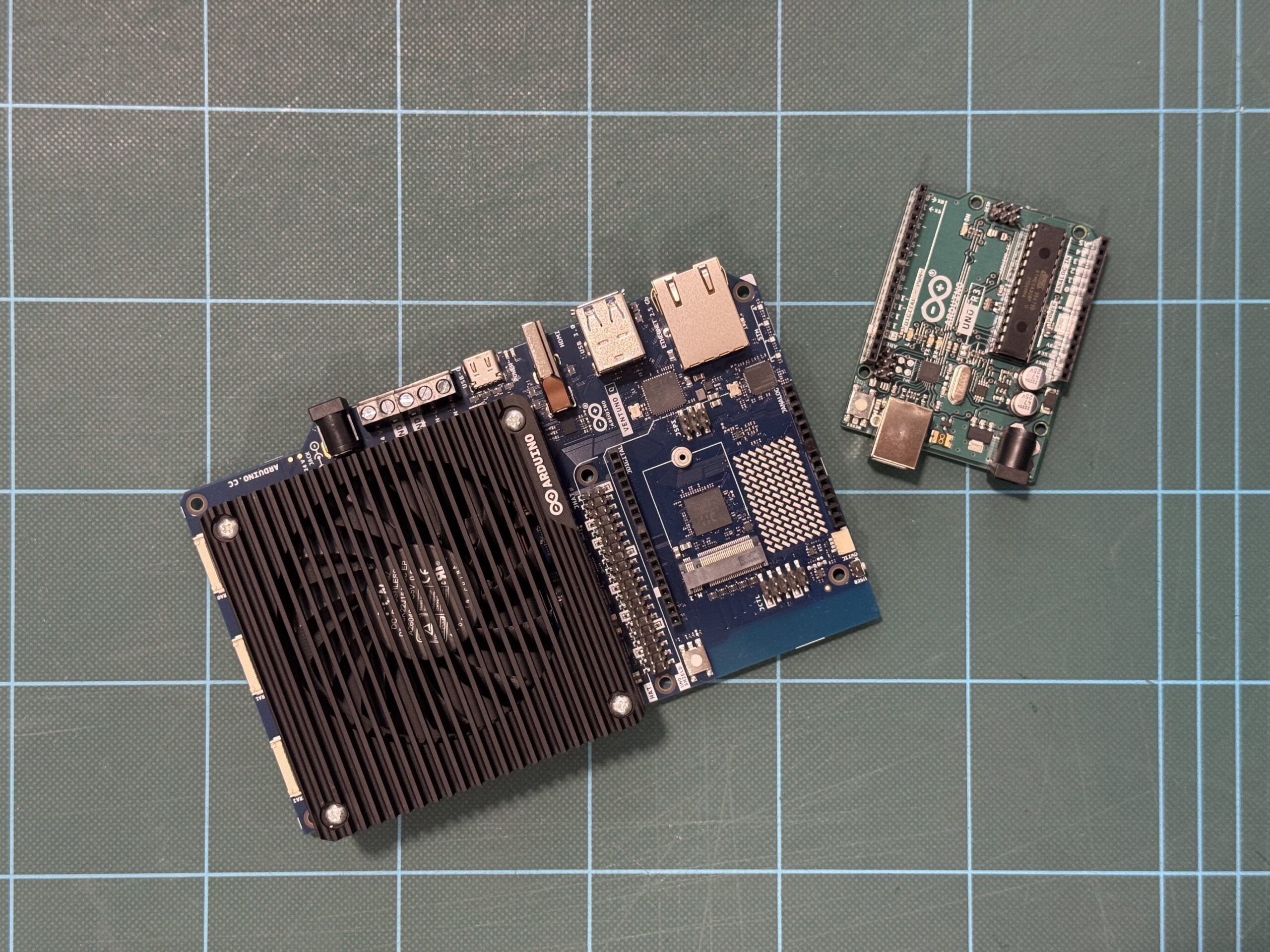
Sitting on my desk I have two boards. They carry the same logo, have a somewhat similar name. Their technology could not be more different, and yet the philosophy behind them is exactly the same.
On the left I have an early Arduino® UNO Rev3, featuring a Microchip ATmega328P, a fingernail-sized piece of silicon dating back the 2000s, that powered the original Arduino revolution. On the right sits the Arduino® VENTUNO Q, running a Qualcomm Dragonwing IQ-8 chipset with eight-core CPU and an NPU able to go up to 40 dense TOPS, making it the most capable AI-focused Arduino boards to date.
Both are Arduino. Both share the same pin headers. In just a few steps, you can blink an LED on one, or on the other deploy an 8-billion parameter LLM, then ask it how to program the original board to blink an LED.
Crazy how technology has evolved in the last 20 years, but naturally the obvious question is by how much exactly?
Well, you already know the answer from the headline, but getting to the real figure reveals a common pitfall in how performance specifications are presented and offers a better way to evaluate any performance claim.
The problem with specs
The Dragonwing chipset (IQ-8275) on VENTUNO Q carries a headline specification of 40 dense TOPS, representing forty trillion dense operations per second.
The 2009 ATmega328P is, on the other hand, the workhorse of the embedded electronics world: a single 8-bit AVR RISC core clocked at 20Mhz, known for its long-standing use in embedded applications, straightforward architecture, and broad accessibility.
The ATmega has no performance metric on its datasheet because nobody was tracking this type of stuff back then. But, if you estimate its compute ceiling manually, you land at roughly 8 million operations per second.
Divide 40 trillion by 8 million and you get 5 million. Case closed?
Not quite. That simple division hides a common trap in how performance numbers are interpreted: operations aren’t created equal.
Computers do math in different formats: think of them as different currencies. Small integer formats (often used for basic pixel brightness) require relatively few computational resources. High-precision floating-point decimals (often used for physics or navigation) typically require more computational resources. As a result, a chip optimized to blast through basic integers can look ordinary when forced to handle complex decimals.
Marketing materials for AI hardware usually quote the small-integer format, INT8 or INT16. Comparing those figures with an ATmega328P estimate derived from general-purpose clock cycles is similar to comparing different currencies without applying an exchange rate. The resulting number may appear dramatic, but it does not provide a meaningful like-for-like comparison.
So here’s Rule #1 of meaningful performance comparisons: both sides must be measured using the same “currency.”
Designing a fair race
To run a meaningful comparison, both chips should perform the same operation on the same data and produce equivalent results.
A representative workload for this operation is the mathematical backbone of modern machine learning: multiplying two numbers, adding the result to a running total. It’s called multiply-accumulate or, colloquially, MAC.
Repeat this loop millions (or trillions) of times, and you can get to things such as Image Classification (aka deciding whether a photo contains a dog, a car, or a birthday cake), Voice Recognition (aka continuously looking for a specific wake word while filtering out background noise) or even funkier stuff like Autonomous Navigation (aka evaluating sensor data in real time to distinguish a wall from a person).
These tasks are all the same underlying math, an aggregation of MAC operations, just at different scales, making them a useful ruler.
The actual benchmark
Let’s go for image classification to keep things simple.
We’ll need test images to be fed into both systems, originated as standard digital photos cropped and resized to a uniform resolution of 224 × 224 pixels across three RGB color channels. This preprocessing converts each photograph into an input data array (aka a tensor) containing 150,528 individual pixel values (224 times 224 times 3). The image data is formatted as 8-bit quantized integers (INT8), mapping every color value to a whole number between 0 and 255 to match the low-precision integer format required by modern hardware.
Evaluating one photo requires streaming this tensor through a vision model containing roughly 100 megabytes of stored parameters, generating a workload of 8 billion total operations (4 billion MAC steps). VENTUNO Q is designed to process roughly 5,000 photos every second; at that rate, the system could sort an entire photo archive (or just a fancy meal worth of pictures of a millennial) in a single heartbeat. Under the same benchmark assumptions, the original UNO Rev3 would take about 17 minutes to analyze the same photo, so think twice before taking a pic of that tiramisu.
To process the 5,000 photos that VENTUNO Q is built to handle in one second, UNO Rev3 would need approximately 58 days at the benchmarked throughput rate. If you started on January 1st, it wouldn’t finish until late February.
Within the context of this benchmark, the performance difference remains on the order of five million to one.
Why this is actually all meaningless
Here’s the catch: UNO Rev3 cannot practically execute this benchmark workload because the model exceeds the device’s available memory resources.
An AI vision model requires roughly 100 megabytes of memory to store its parameters. The ATmega328P has 32 kilobytes of flash memory and 2 kilobyte of RAM, which is insufficient to store the model.
The “58-day” metric just assumes the infinite external memory attached. It’s a mere thought exercise, but there is something even more relevant.
The gap between 2008 and today isn’t just that the old chip is slow. It’s that an entire category of work moved from impractical on earlier hardware to routinely achievable on modern AI platforms. No amount of patience can stretch 8 kilobytes of memory into 100 megabytes.
Real technological leaps rarely feel like “the same thing, faster.” They manifest as entirely new categories of capabilities opening up for the first time.
What does really matter
While this thought exercise suggests a five-million-fold difference in arithmetic capability, the significance of VENTUNO Q extends beyond raw compute performance.
One of the platform’s key contributions is helping make edge intelligence more accessible by lowering barriers to experimentation and development. The goal is to make it easier for developers to move from exploring AI software to building physical AI systems.
Whether toggling a GPIO pin on an 8-bit ATmega or deploying a computer vision model on a modern NPU, both boards are built around a similar development philosophy: connect the hardware, open an accessible development environment, and begin building.
That emphasis on developer accessibility is what matters most. Despite substantial differences in compute capability, both boards are designed to provide an approachable path into hardware development and experimentation.
Preserving accessibility while dramatically expanding compute capabilities represents a significant engineering achievement. For me, that is the real story. Making AI technologies more accessible helps more people move from using AI tools to building AI-enabled applications of their own.
Qualcomm branded products are products of Qualcomm Technologies, Inc. and/or its subsidiaries. Arduino, UNO, and VENTUNO, and the Arduino logo are trademarks or registered trademarks of Arduino S.r.l.